
Overview
A review of replacing the existing Raspberry Pi + RS485 TO USB setup with an RS485-WiFi converter to improve maintainability for controlling a Hyundai Communication wallpad with Home Assistant.
Steps
1. Previous Setup
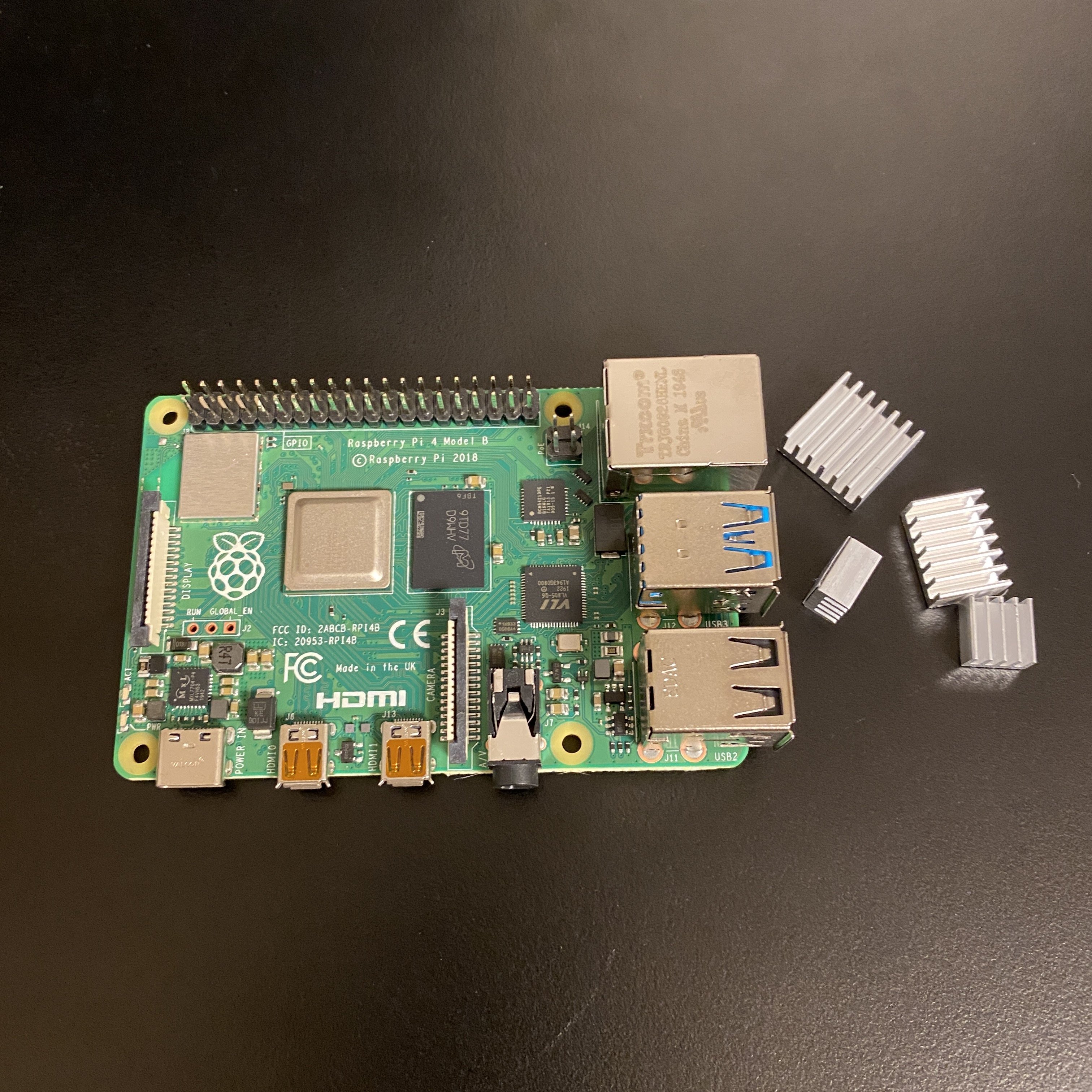
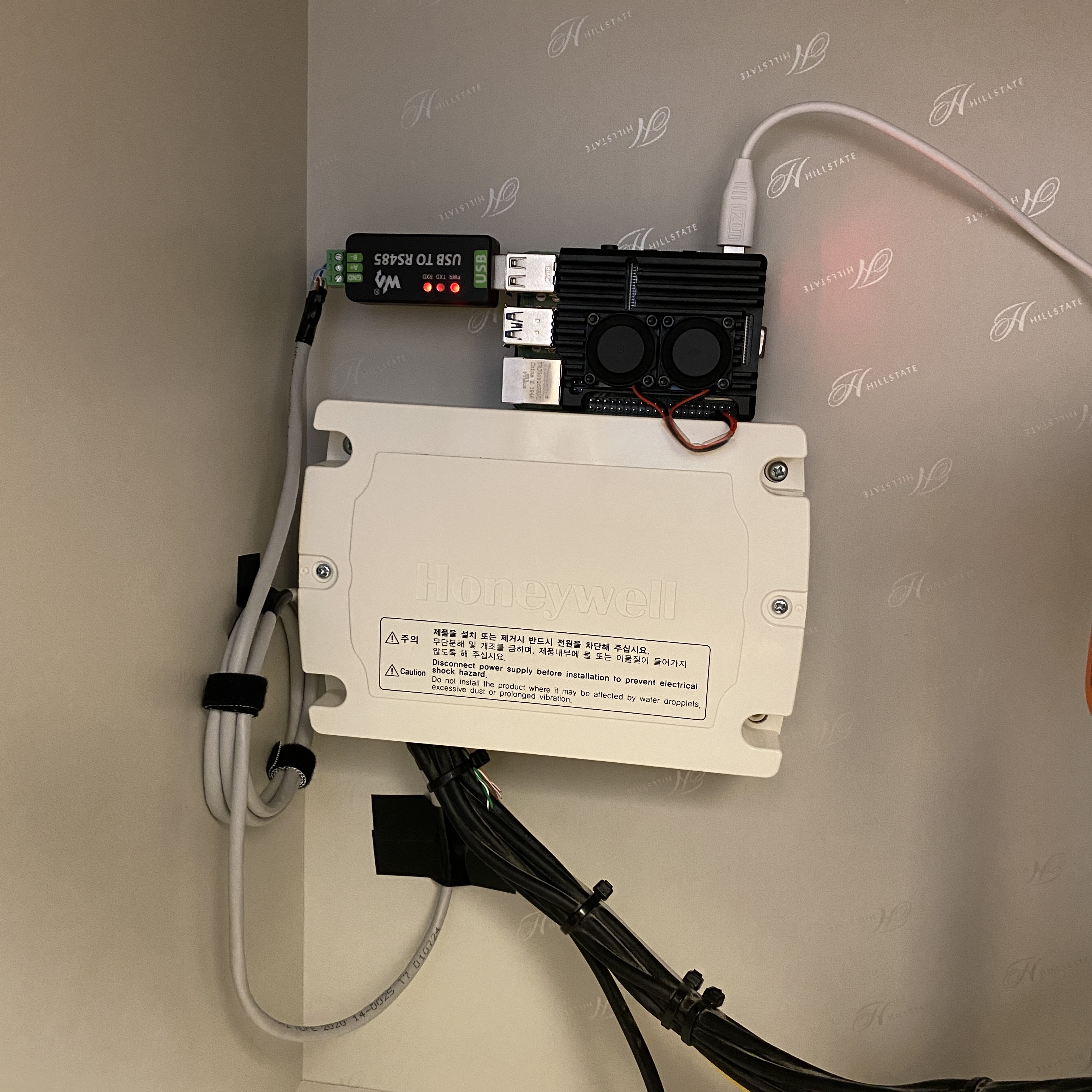
The previous setup consisted of a Raspberry Pi 4 running Home Assistant with an RS485 TO USB converter directly connected via USB to control the wallpad.
While the system functioned correctly, maintenance proved more difficult than expected. Having the Home Assistant server and RS485 interface tied to a single Raspberry Pi made server replacement or relocation difficult, and SD card longevity was a constant concern.
Switching to an RS485-WiFi converter would allow the Home Assistant server to run on a separate device (NAS, mini PC, etc.) with only the converter placed near the wallpad, making maintenance much easier. This post reviews the hardware configuration and setup process for the replacement.
2. System Architecture
To control a Hyundai Communication (IMAZU) wallpad from Home Assistant, you need to connect an RS485-WiFi converter to the wallpad’s RS485 bus and relay packets over a TCP/IP network. The overall system architecture is as follows.
+----------+          +---------------------------+          +--------+          +-----------+
| Wallpad  |  RS485   | RS485-WiFi Converter      |  WiFi    | Router |  LAN     | HA Server |
| (IMAZU)  |==========| (Waveshare/HF2211S/EW11A) |==========|        |==========|           |
+----------+  A+/B-   +---------------------------+  TCP/IP  +--------+          +-----------+
      |
      | RS485 Bus
      |
+----------------+
| Light, Heating |
| Gas, Fan, AC   |
+----------------+
The wallpad controls various devices such as lights, heating, gas valves, ventilation fans, and air conditioners through the RS485 bus. The RS485-WiFi converter connects in parallel to this bus, receives packets, and forwards them to the Home Assistant server.
3. Parts List
3.1. Required Parts
| Part | Purpose |
|---|---|
| RS485-WiFi Converter | Converts RS485 signals to TCP/IP. Choose from the Waveshare RS485 TO WIFI/ETH, Waveshare RS232/485 TO WIFI ETH (B), Hi-Flying HF2211S, or Hi-Flying EW11A-0. |
| DC Adapter (5V or 12V) | Powers the RS485-WiFi converter. Select the appropriate voltage for your converter. |
| UTP Cable (Cat.5e or higher) | Used for RS485 A+/B- signal wiring. Required if no existing wiring is available. |
| Home Assistant Server | The home automation server that receives wallpad packets and controls devices. |
3.2. RS485-WiFi Converter Comparison
| Feature | Waveshare RS485 TO WIFI/ETH | Waveshare RS232/485 TO WIFI ETH (B) | Hi-Flying HF2211S | Hi-Flying EW11A-0 |
|---|---|---|---|---|
| Connectivity | WiFi + Ethernet (RJ45) | WiFi + Ethernet (RJ45) | WiFi only | WiFi only |
| Power | Screw terminal (5–36V) or PoE | DC 5.5mm jack + screw terminal (6–36V), PoE capable | Screw terminal (5–36V) | Screw terminal (5–18V) or DC jack |
| RS485 Connection | Screw terminal (A+, B-, GND) | Screw terminal (A+, B-) | Screw terminal (A, B, GND) | Screw terminal (A+, B-, VCC, GND) |
| Enclosure | Plastic | Metal case (84x64x24mm) | Plastic (79x53x25mm) | Plastic |
| Configuration | Web UI (browser) | Web UI (browser) | Web UI (browser) | Web UI (browser) |
| Pros | Ethernet support for stability, PoE capable | DC jack for easy power connection, metal enclosure, PoE capable | Wide voltage range (5–36V), RS485 8kV ESD protection | Small form factor, easy to install in tight spaces |
| Cons | Screw terminal power connection is inconvenient | Relatively higher price | WiFi-only, internal antenna with lower reception sensitivity | WiFi-only, potentially unstable depending on environment |
If wired Ethernet is available, the Waveshare is recommended. If space is limited or only WiFi is available, the EW11A-0 is a better choice. If a wide input voltage range or ESD protection is important, choose the HF2211S. If dealing with screw terminals is inconvenient, consider the RS232/485 TO WIFI ETH (B) model which supports a DC 5.5mm jack.
3.3. Supplementary Parts
| Part | Purpose |
|---|---|
| DC Jack to Screw Terminal Adapter | Convenient for connecting a DC adapter to the EW11A-0. |
| Silicone Wire (AWG 22–24) | Used for extending RS485 wiring. Has excellent heat resistance. |
| Ferrule Terminals | Securely fasten wires to screw terminals. |
| Electrical Tape or Heat Shrink Tubing | Insulates exposed wire connections. |
4. RS485 Basics
4.1. What is RS485 Communication
RS485 is a differential signal-based serial communication standard widely used in industrial applications. It supports multi-drop topology, allowing multiple devices to share a single bus, with a maximum communication distance of 1,200 meters. In apartment wallpad systems, the wallpad (master) and various devices (slaves) share a single RS485 bus for communication.
4.2. A+/B- Differential Signaling
RS485 transmits data using the voltage difference between two signal lines, A+ and B-.
        A+ -----+     +-----+     +-----
                |     |     |     |
        B- -+   | +---+     +---+ |
            |   | |             | |
            +---+ +-------------+ +-----

        Logic 1: A+ > B- (positive)
        Logic 0: A+ < B- (negative)
Even if external noise is induced on both signal lines equally, the voltage difference is maintained, making it highly resistant to noise. This characteristic allows stable operation even over long wiring distances inside apartments.
4.3. 9600 Baud, 8N1 Configuration
The Hyundai Communication wallpad uses the following RS485 communication parameters.
| Parameter | Value | Description |
|---|---|---|
| Baud Rate | 9600 | Transmits 9600 bits per second. |
| Data Bits | 8 | Each frame contains 8 data bits. |
| Parity | None (N) | No parity bit is used. |
| Stop Bits | 1 | Uses 1 stop bit. |
These settings must be identically configured on the RS485-WiFi converter’s serial parameters.
5. Hyundai Wallpad RS485 Wiring
5.1. Wallpad Junction Box Layout
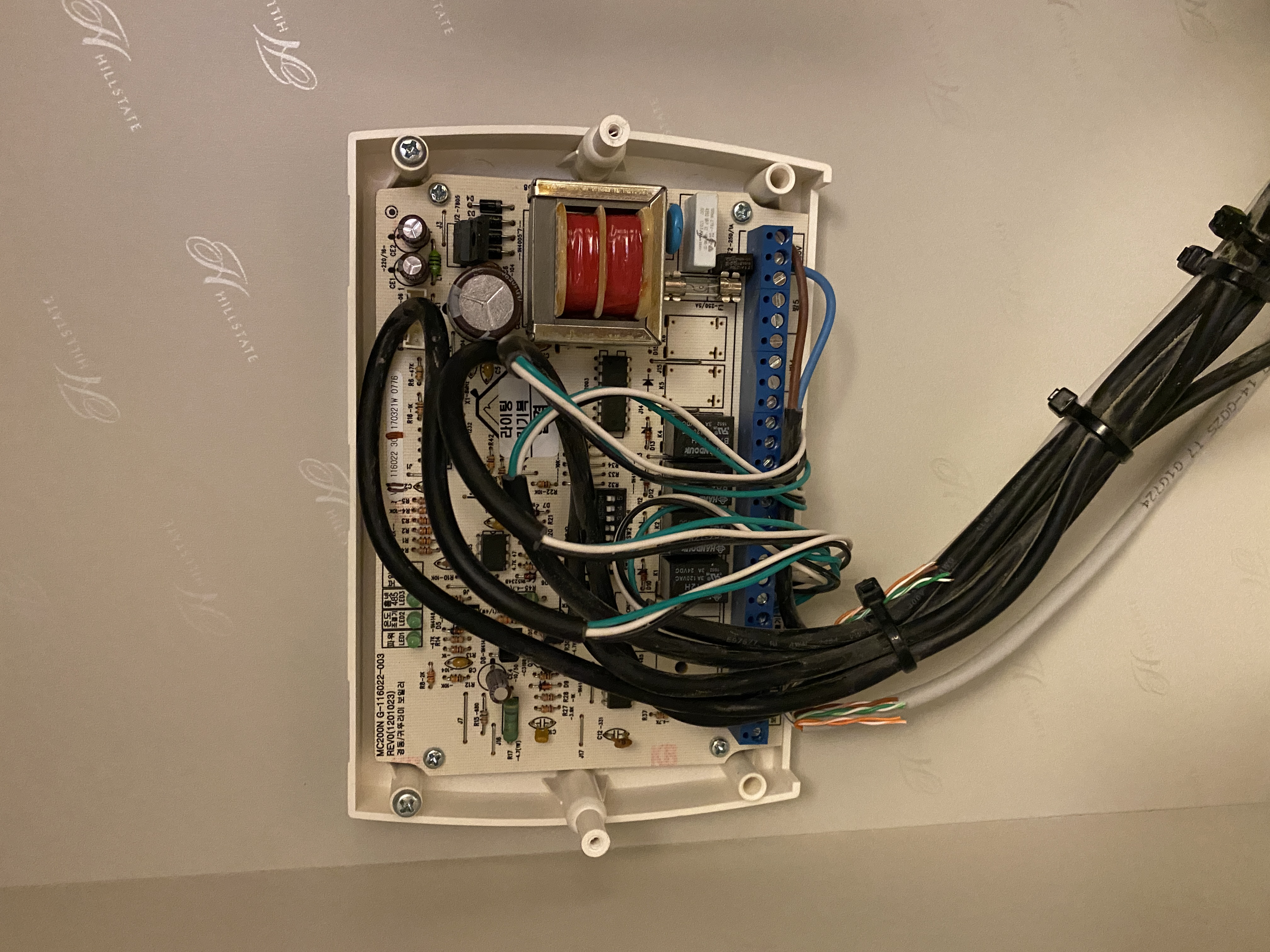
The RS485 communication lines in an apartment are typically concentrated in the communication junction box (distribution box) near the entrance or behind the wallpad. The typical wiring structure of a Hyundai Communication wallpad system is as follows.
+----------------------------------------------------+
|                  Junction Box                      |
|                                                    |
|  +-----------+  +-----------+  +--------------+    |
|  | Wallpad   |  | Sub-phone |  | Honeywell    |    |
|  | RS485     |  | RS485     |  | Water Dist.  |    |
|  | A+  B-    |  | A+  B-    |  | A+  B-       |    |
|  +--+---+----+  +--+---+----+  +--+---+-------+    |
|     |   |          |   |          |   |            |
|     +---+----------+---+----------+---+            |
|              RS485 Bus (Daisy Chain)               |
+----------------------------------------------------+
The RS485 bus is connected in a daisy-chain topology where A+ connects to A+ and B- connects to B-.
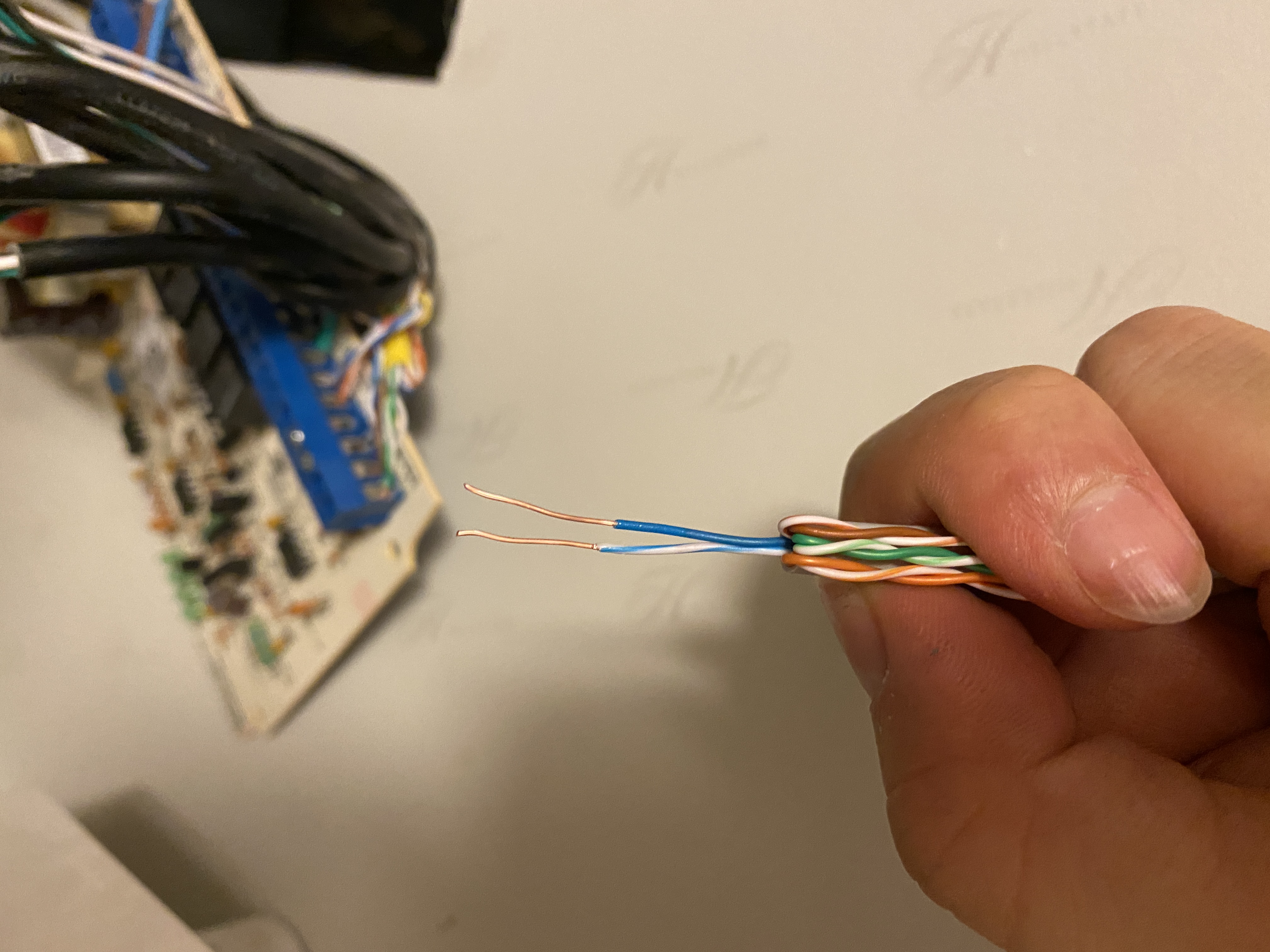
5.2. Finding the RS485 A+/B- Lines
Here is how to find the RS485 communication lines inside the junction box.
- Check the connectors behind the wallpad for terminals labeled RS485
- They typically consist of 2 wires (A+, B-); colors may vary depending on the installer
- Measuring the voltage between the two wires with a multimeter will show fluctuations in the 0–5V range during active communication
- When communication is idle, you will measure approximately 0V or a steady DC voltage
5.3. Wiring from the Honeywell Water Distributor
If a Honeywell water distributor is installed for heating control, you can branch the connection from its RS485 terminals.
+------------------------------+
|   Honeywell Water Dist.      |
|                              |
|   [A+] [B-]    [A+] [B-]     |
|    IN             OUT        |
+---+----+--------+----+-------+
    |    |        |    |
    |    |        |    +---- B- ---- RS485-WiFi Conv. B-
    |    |        +--------- A+ ---- RS485-WiFi Conv. A+
    |    +------------------ B- ---- Wallpad B-
    +----------------------- A+ ---- Wallpad A+
Branch from the OUT terminals of the water distributor to the RS485-WiFi converter. The IN terminals carry the existing wiring from the wallpad.
5.4. Wiring from Behind a Sub-phone
RS485 wiring may also be accessible behind sub-phones (intercoms) in the living room or bedrooms. Wiring from behind a sub-phone saves you from accessing the junction box.
+----------------------+
|   Behind Sub-phone   |
|                      |
|   [A+] [B-] [etc]    |
+---+----+-------------+
    |    |
    |    |    Existing RS485 Bus (Wallpad)
    |    |
    |    +------- B- ---- RS485-WiFi Conv. B-
    +------------ A+ ---- RS485-WiFi Conv. A+
Keep the existing wiring intact and connect the RS485-WiFi converter in parallel to the A+/B- lines.
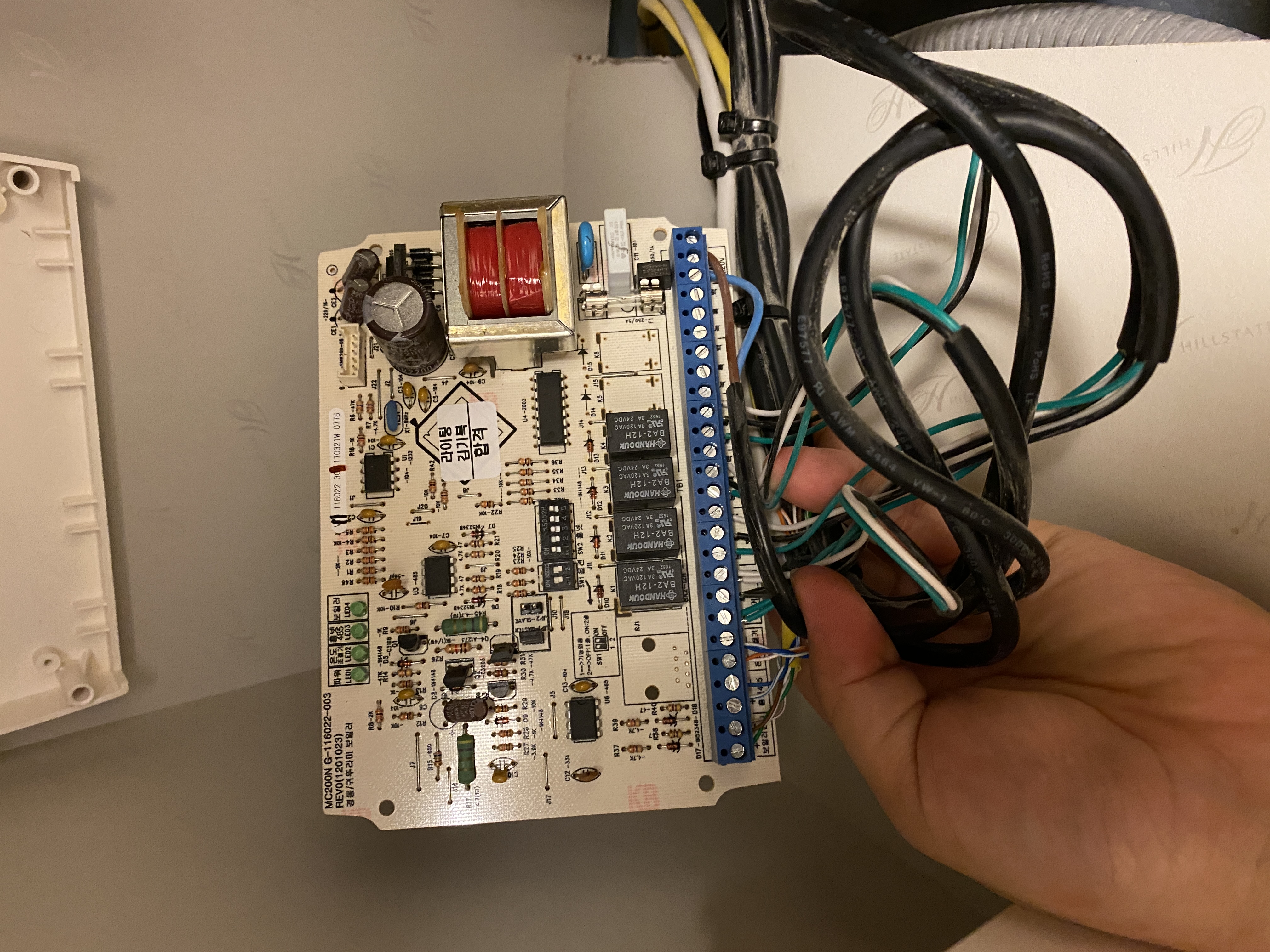
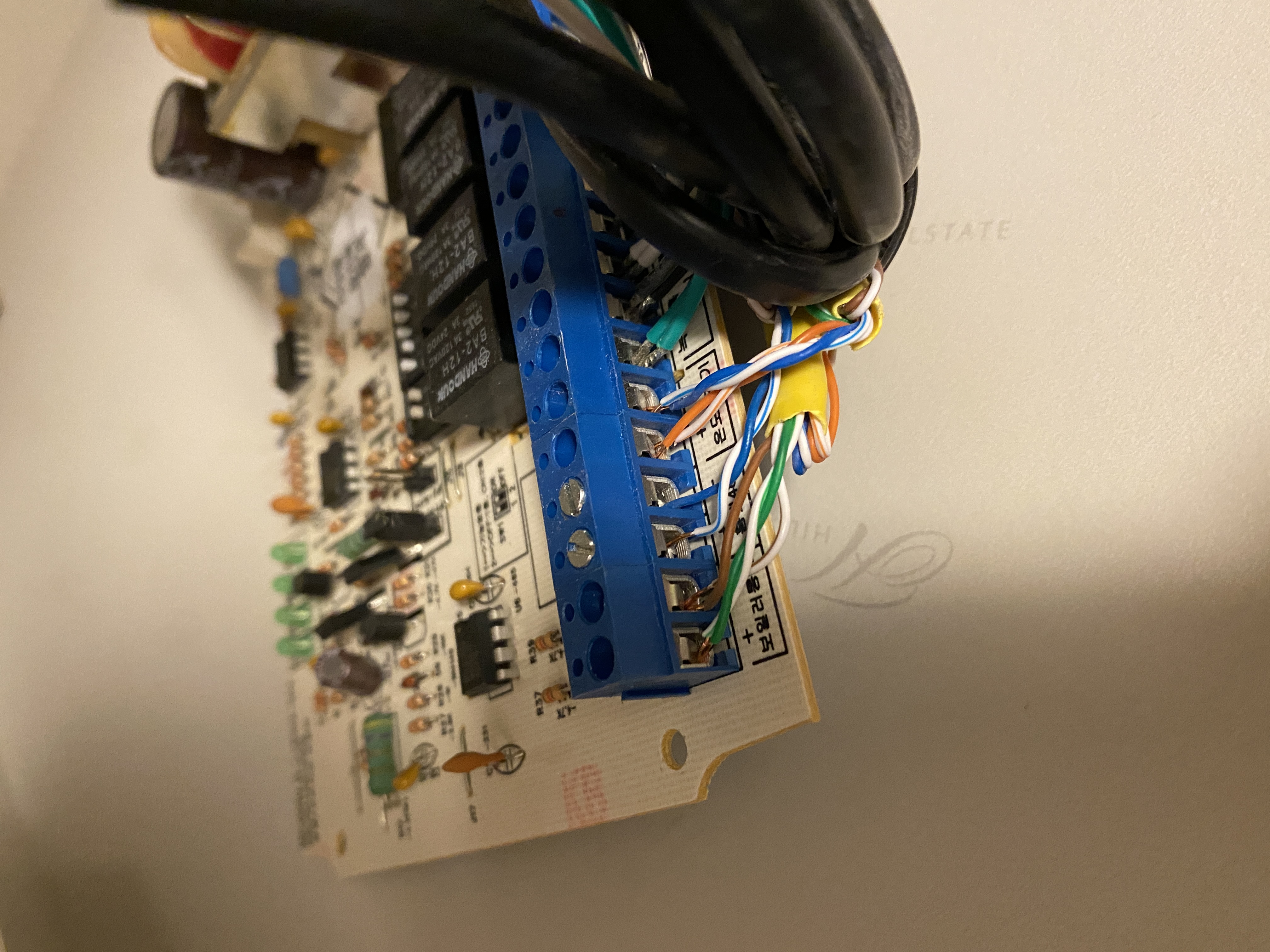
5.5. Wiring from Behind the Wallpad
Wiring directly from behind the wallpad is the most reliable method. Branch directly from the wallpad’s RS485 terminals.
+------------------------------+
|   Behind Wallpad             |
|                              |
|   [A+] [B-] [VCC] [GND]      |
+---+----+---------------------+
    |    |
    |    |    Existing RS485 Bus (Devices)
    |    |
    |    +------- B- ---- RS485-WiFi Conv. B-
    +------------ A+ ---- RS485-WiFi Conv. A+
Branch only the A+ and B- lines from the wallpad’s RS485 terminals to the RS485-WiFi converter. Do not use VCC and GND (wallpad power) for powering the converter.
6. Power Supply
6.1. Waveshare Power Supply
The Waveshare RS485 TO WIFI/ETH can be powered in two ways.
Method 1: DC Adapter (WiFi Mode)
Connect a 5–36V adapter to the screw terminal (VIN/GND). This is the simplest method.
+---------------------+
|     Waveshare       |
|                     |
|  [VIN 5~36V] ---------- DC Adapter (+)
|  [GND]       ---------- DC Adapter (-)
|                     |
|  [A+] ----------------- RS485 A+
|  [B-] ----------------- RS485 B-
|                     |
|  [WiFi Antenna]     |
+---------------------+
Method 2: PoE (Wired Ethernet Mode)
Using a PoE switch or PoE injector allows you to supply both data and power through a single Ethernet cable.
+---------------------+              +--------------------+
|     Waveshare       |    Cat.5e    |  PoE Switch        |
|                     |              |  or Injector       |
|  [RJ45] -----------------------------  [RJ45 + PoE]     |
|                     |              +--------------------+
|  [A+] ---- RS485 A+ |
|  [B-] ---- RS485 B- |
+---------------------+
PoE eliminates the need for a separate power adapter, resulting in a cleaner installation.
The RS232/485 TO WIFI ETH (B) model supports a DC 5.5mm jack, allowing direct adapter connection without dealing with screw terminals. The input voltage range is 6–36V and PoE is also supported.
+-----------------------------+
|  RS232/485 TO WIFI ETH (B)  |
|                             |
|  [DC 5.5mm Jack] ------------ DC Adapter (6~36V)
|                             |
|  [A+] ----------------------- RS485 A+
|  [B-] ----------------------- RS485 B-
|                             |
|  [WiFi Antenna]             |
+-----------------------------+
6.2. HF2211S Power Supply
The HF2211S receives power through its screw terminals. It accepts a wide input voltage range of 5–36V, allowing various adapters to be used.
+------------------------------+
|          HF2211S             |
|                              |
|   [A] [B] [GND] [V+] [GND]   |
+---+---+----+-----+-----+-----+
    |   |    |     |     |
    |   |    |     |     +---- GND ---- DC Adapter (-)
    |   |    |     +---------- V+  ---- DC Adapter (+) (5~36V)
    |   |    +---------------- GND ---- (RS485 GND, optional)
    |   +--------------------- B   ---- RS485 B-
    +------------------------- A   ---- RS485 A+
6.3. EW11A-0 Power Supply
The EW11A-0 receives power through its screw terminals. The pin layout is as follows.
+------------------------------+
|          EW11A-0             |
|                              |
|   [A+] [B-] [VCC] [GND]      |
+---+----+-----+------+--------+
    |    |     |      |
    |    |     |      +---- GND ---- DC Adapter (-)
    |    |     +----------- VCC ---- DC Adapter (+) (5~18V)
    |    +----------------- B-  ---- RS485 B-
    +---------------------- A+  ---- RS485 A+
If using an adapter with a DC jack connector, a DC jack-to-screw terminal adapter is convenient.
DC Adapter ---- [DC Jack] ---- [Screw Terminal Adapter] ---- EW11A-0 [VCC/GND]
Keep the following in mind when supplying power.
- Use a certified power adapter (fire prevention)
- Verify the adapter output voltage is within the 5–18V range
- Always check VCC and GND polarity before connecting (reverse polarity can cause damage)
- Use heat-resistant silicone wire (AWG 22–24) when installing inside a junction box
7. Waveshare Initial Setup
The RS232/485 TO WIFI ETH (B) model uses the same web UI, so the setup procedure is identical.
7.1. WiFi Connection Setup
The initial setup procedure for the Waveshare device is as follows.
- Power on the Waveshare and its built-in AP will activate
- Connect to the
Waveshare_xxxxAP from a PC or smartphone - Open a browser and navigate to
http://10.10.100.254 - Go to WiFi settings from the left menu
- Enable STA Mode and enter your home router’s SSID and password
- Save the settings and reboot the device
7.2. TCP Server Mode Configuration
To receive packets via TCP socket in Home Assistant, configure TCP Server mode.
| Setting | Value |
|---|---|
| Working Mode | TCP Server |
| Local Port | 8899 |
| Max Clients | 4 (default) |
7.3. Serial Parameter Configuration
Match the wallpad’s RS485 communication parameters.
| Setting | Value |
|---|---|
| Baud Rate | 9600 |
| Data Bits | 8 |
| Parity | None |
| Stop Bits | 1 |
| Flow Control | Disable |
7.4. Static IP Assignment
Since Home Assistant will lose connection if the converter’s IP changes, a static IP must be assigned. There are two methods.
- Router DHCP Reservation: Assign a static IP to the Waveshare’s MAC address in your router’s admin page
- Device Static IP Setting: Set the IP to Static in the Waveshare web UI under STA Mode and manually enter the IP, subnet mask, and gateway
Router DHCP reservation is recommended. Setting a static IP directly on the device requires reconfiguration when changing routers.
8. HF2211S Initial Setup
The HF2211S is from the same manufacturer (Hi-Flying) as the EW11A-0 and shares the same web UI. The only difference is the AP name being HF2211S_xxxx. The rest of the setup procedure is identical to the EW11A-0 section below.
9. EW11A-0 Initial Setup
9.1. WiFi Connection Setup (AP Mode → STA Mode)
The initial setup procedure for the EW11A-0 is as follows.
- Power on the EW11A-0 and its built-in AP will activate
- Connect to the
EW11A-0_xxxxAP from a PC or smartphone - Open a browser and navigate to
http://10.10.100.254 - Log in at System Settings with the default credentials (admin/admin)
- Select STA Mode in WiFi Settings
- Click the Scan button to list nearby access points
- Select your home router’s SSID and enter the password
- Save the settings and reboot the device
After rebooting, the EW11A-0 will automatically connect to your router. Check the assigned IP in your router’s admin page and access it via browser to proceed with the remaining settings.
9.2. TCP Server Mode Configuration
Configure the following in Communication Settings.
| Setting | Value |
|---|---|
| Protocol | TCP Server |
| Local Port | 8899 |
| Max Clients | 4 |
9.3. Serial Parameter Configuration
Configure the following in Serial Port Settings to match the wallpad’s RS485 communication parameters.
| Setting | Value |
|---|---|
| Baud Rate | 9600 |
| Data Bits | 8 |
| Parity | None |
| Stop Bits | 1 |
| Flow Control | Disable |
9.4. Static IP Assignment
As with the Waveshare, router DHCP reservation is recommended. The EW11A-0 web UI also supports static IP configuration, but it requires reconfiguration when changing routers.
10. Communication Test
10.1. Verifying Packet Reception via TCP Socket
Once the RS485-WiFi converter setup is complete, verify that wallpad packets are being received correctly through the TCP socket. The following Python code can be used for testing.
import socket

HOST = "192.168.x.x"   # RS485-WiFi converter IP address
PORT = 8899            # TCP Server port

with socket.socket(socket.AF_INET, socket.SOCK_STREAM) as s:
    s.connect((HOST, PORT))
    print(f"Connected to {HOST}:{PORT}")

    while True:
        data = s.recv(1024)
        if data:
            hex_data = data.hex()
            print(f"Received: {hex_data}")
If the wallpad is communicating normally, packets will be received periodically.
10.2. Hyundai Communication Packet Structure
The RS485 packet structure of the Hyundai Communication (IMAZU) wallpad is as follows.
+--------+------+--------+------+------+------+------+------+----------+------+
| Header | Len  | 01/1a  | Dev  | Cmd  | Func | Sub  | Val  |   Data   | Tail |
|  0xF7  |      |        |      |      |      |      |      |          | 0xEE |
+--------+------+--------+------+------+------+------+------+----------+------+
| Field | Description |
|---|---|
| Header | Packet start byte 0xF7 |
| Len | Total packet length (including Header through Tail) |
| 01/1a | Device protocol identifier (01: general, 1a: heating) |
| Dev | Device type (Light: 19, Heating: 18, Gas: 1b, AC: 1c, Switch: 1f, Fan: 2b, etc.) |
| Cmd | Command type (Scan: 01, Control: 02, Status: 04) |
| Func | Function code (On/Off: 40, Temperature: 45, Mode: 46, etc.) |
| Sub | Room number and sub-device ID |
| Val | Value (On: 01, Off: 02, etc.) |
| Data | Additional data (variable length depending on device) |
| Checksum | XOR checksum (XOR of all bytes from Header to Data) |
| Tail | Packet end byte 0xEE |
10.3. Normal Reception Example
When packets are being received normally, output will look similar to the following.
Connected to 192.168.x.x:8899
Received: f7xx0119xxxxxxxxxxxxxxxxee    # Light status response
Received: f7xx0118xxxxxxxxxxxxxxxxee    # Heating status response
Received: f7xx011bxxxxxxxxxxxxxxxxee    # Gas valve status response
If packets starting with f7 and ending with ee are received periodically, the wiring and converter setup have been completed successfully.
11. Precautions and Troubleshooting
11.1. Symptoms of Reversed RS485 Polarity (A+/B-)
If A+ and B- are connected in reverse, the following symptoms may occur.
- No data is received on the TCP socket
- Intermittently corrupted data (incorrect bytes) is received
- Meaningless packets that do not start with
f7are received
In this case, swap the A+ and B- connections on the RS485-WiFi converter and try again. Reversing RS485 polarity does not damage the device, so you can safely swap the connections.
11.2. Common GND Connection
While the RS485 specification allows communication with just the A+/B- lines, connecting a common GND is recommended when the RS485-WiFi converter uses a separate power supply. Without a common GND, the reference voltage between the two devices may differ, causing intermittent communication errors or packet loss. Connecting the converter’s GND terminal to the RS485 GND of the wallpad or water distributor improves stability.
11.3. Symptoms of Insufficient Power
If the RS485-WiFi converter does not receive sufficient power, the following symptoms may occur.
- The device reboots repeatedly
- WiFi connection drops frequently
- TCP connection is established but no packets are received
Verify that the adapter’s output current meets the converter’s specifications. Generally, 5V 1A or higher is sufficient.
11.4. Dealing with WiFi Disconnections
If the RS485-WiFi converter frequently disconnects in a WiFi environment, check the following.
- Static IP Assignment: Prevents disconnections caused by DHCP lease renewal failures
- Fixed WiFi Channel: Set the router’s WiFi channel to a specific channel instead of auto. Automatic channel switching can cause reconnection delays
- Use 2.4GHz: Has better wall penetration than 5GHz, providing more stable connections inside junction boxes
- Converter Placement: Install as far as possible from metal structures inside the junction box
11.5. Fire Safety Precautions
When installing electronic devices inside a communication junction box, pay attention to fire safety.
- Only use certified power adapters
- Always insulate exposed wire connections with electrical tape or heat shrink tubing
- Do not place combustible materials (paper, styrofoam, etc.) inside the junction box
- Arrange wires with sufficient slack to prevent bending or pinching
- Periodically check for heat generation after installation


Leave a comment